Harley-Davidson motorcycles are synonymous with power, performance, and a legacy of engineering excellence. One of the essential components for diagnosing and maintaining these legendary machines is the Harley Davidson 3 pin data port wiring diagram. This wiring diagram is crucial for understanding how the motorcycle’s onboard systems communicate and integrate, especially when connecting diagnostic tools or troubleshooting electronic issues. This article delves into the details of the Harley Davidson 3 pin data port wiring diagram, exploring its structure, purpose, and practical applications.
What is the Harley Davidson 3 Pin Data Port?
The Harley Davidson 3 pin data port is a standardized interface that allows technicians and enthusiasts to access the motorcycle’s electronic systems. This port is integral for diagnostics, firmware updates, and monitoring real-time data. Its wiring diagram provides a detailed view of how the data port connects to various components, enabling efficient troubleshooting and maintenance.
Key Components of the Harley Davidson 3 Pin Data Port Wiring Diagram
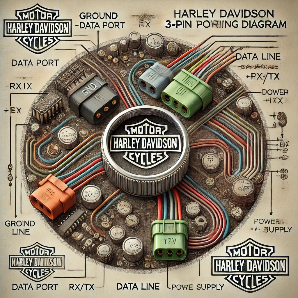
To understand the Harley Davidson 3 pin data port wiring diagram, it’s essential to familiarize yourself with its key components. The 3-pin port typically consists of three essential connections:
- Ground (GND): This pin connects the data port to the motorcycle’s electrical ground, completing the circuit for communication.
- Data Line (RX/TX): The data line serves as the communication channel between the motorcycle’s Electronic Control Unit (ECU) and external diagnostic tools.
- Power Supply (+12V): This pin supplies power to the data port and diagnostic devices connected to it.
Each of these pins plays a vital role in ensuring the seamless transfer of information and commands between the motorcycle and the diagnostic tool.
Importance of the Harley Davidson 3 Pin Data Port Wiring Diagram
The Harley Davidson 3 pin data port wiring diagram is invaluable for several reasons. It provides a clear roadmap for understanding the electrical connections associated with the data port. Whether you are diagnosing a fault, installing aftermarket accessories, or performing routine maintenance, the wiring diagram serves as a guide to prevent errors and ensure proper functionality.
This diagram is also critical for identifying potential issues in the communication system. For example, if a diagnostic tool fails to connect, the wiring diagram can help pinpoint whether the problem lies in the ground connection, data line, or power supply.
Read Also: Craftsman 7.0Amp Corded Drill 1/2: A Comprehensive Guide
How to Read the Harley Davidson 3 Pin Data Port Wiring Diagram
Reading a Harley Davidson 3 pin data port wiring diagram requires a basic understanding of electrical schematics. Here’s a step-by-step guide to interpreting the diagram:
- Identify the Pins: Locate the three pins labeled as ground (GND), data line (RX/TX), and power supply (+12V).
- Trace the Connections: Follow the wiring paths to see how each pin connects to other components, such as the ECU and battery.
- Check for Color Codes: Many wiring diagrams include color codes for wires, which help identify connections during physical inspection.
- Verify Continuity: Use the diagram to test the continuity of each wire with a multimeter, ensuring that the connections are intact.
By mastering these steps, you can effectively use the Harley Davidson 3 pin data port wiring diagram for diagnostics and maintenance.
Applications of the Harley Davidson 3 Pin Data Port Wiring Diagram
The Harley Davidson 3 pin data port wiring diagram has a wide range of applications, making it a must-have tool for technicians and DIY enthusiasts. Here are some of its key uses:
Diagnostics and Troubleshooting The wiring diagram is essential for diagnosing issues related to the motorcycle’s electronic systems. By understanding the connections outlined in the diagram, you can identify and resolve problems such as faulty sensors, communication errors, and electrical shorts.
Firmware Updates Updating the firmware of the ECU or other electronic modules is another critical application. The wiring diagram ensures that the data port is correctly connected, enabling seamless updates without the risk of damaging the system.
Installing Aftermarket Accessories When installing accessories such as GPS trackers, performance tuners, or custom lighting systems, the wiring diagram helps integrate these components with the motorcycle’s existing systems. This ensures compatibility and prevents electrical conflicts.
Common Issues and Solutions Using the Harley Davidson 3 Pin Data Port Wiring Diagram
Even with its robust design, the Harley Davidson 3 pin data port can encounter issues. The Harley Davidson 3 pin data port wiring diagram is instrumental in diagnosing and resolving these problems. Here are some common issues and their solutions:
Faulty Connections Loose or corroded connections are among the most common problems. Using the wiring diagram, you can identify the affected pins and repair or replace the faulty wires.
Power Supply Issues If the diagnostic tool does not power on, the wiring diagram can help trace the power supply pin and verify its connection to the battery.
Communication Errors Errors in data transmission may occur due to damaged or disconnected data lines. The wiring diagram aids in testing the continuity and integrity of the data line, ensuring proper communication between the ECU and diagnostic tools.
Upgrading and Customizing with the Harley Davidson 3 Pin Data Port Wiring Diagram
For Harley-Davidson enthusiasts who enjoy customizing their motorcycles, the Harley Davidson 3 pin data port wiring diagram is an invaluable resource. Whether you’re adding a custom diagnostic display, integrating a smartphone-based monitoring system, or enhancing the motorcycle’s performance with an ECU tuner, the wiring diagram provides the guidance needed to connect these components safely and effectively.
Tips for Using the Harley Davidson 3 Pin Data Port Wiring Diagram
To make the most of the Harley Davidson 3 pin data port wiring diagram, keep these tips in mind:
- Use the Correct Tools: Always use a reliable multimeter and appropriate connectors to test and repair the wiring.
- Refer to the Manufacturer’s Manual: Cross-check the wiring diagram with the official Harley-Davidson service manual to ensure accuracy.
- Label Wires During Modifications: When making changes to the wiring, label each wire to avoid confusion and ensure proper reassembly.
Conclusion
The Harley Davidson 3 pin data port wiring diagram is a vital tool for anyone working with Harley-Davidson motorcycles. From diagnosing issues to customizing electronic systems, this diagram provides the clarity and guidance needed for successful maintenance and upgrades. By understanding its structure and applications, you can ensure that your motorcycle remains in peak condition, ready to deliver the performance and reliability that Harley-Davidson is known for. Whether you’re a seasoned technician or a passionate DIY enthusiast, the wiring diagram is your key to unlocking the full potential of your Harley-Davidson machine.


