The QS 10 kW hub motor is a key component in the world of electric vehicles (EVs), enabling high efficiency and powerful performance for a variety of applications. Whether it’s electric motorcycles, scooters, or other personal mobility devices, this motor has become a preferred choice for engineers and enthusiasts alike. However, ensuring the motor operates correctly requires a proper understanding of its wiring. This guide explores the essential elements of the QS 10 kW hub motor wiring diagram, offering insights into its components, connections, and best practices for safe and effective use.
Introduction to the QS 10 kW Hub Motor
The QS 10 kW hub motor is renowned for its robust construction, reliability, and impressive performance. It features a three-phase design that makes it ideal for EVs requiring high torque and efficiency. With the capability to deliver substantial power while maintaining low noise and minimal maintenance, it is no surprise that this motor has gained widespread adoption.
Proper wiring is crucial for ensuring optimal performance. The motor’s wiring system involves multiple components that work together to manage power delivery, communication between the controller and the motor, and safety mechanisms. This is where the QS 10 kW hub motor wiring diagram becomes essential, serving as a detailed blueprint for correct installation and operation.
Components of the QS 10 kW Hub Motor Wiring System
Understanding the wiring of the QS 10 kW hub motor begins with familiarizing yourself with its key components. Each wire and connector plays a specific role in the system’s functionality. Below are the primary components involved in the motor’s wiring:
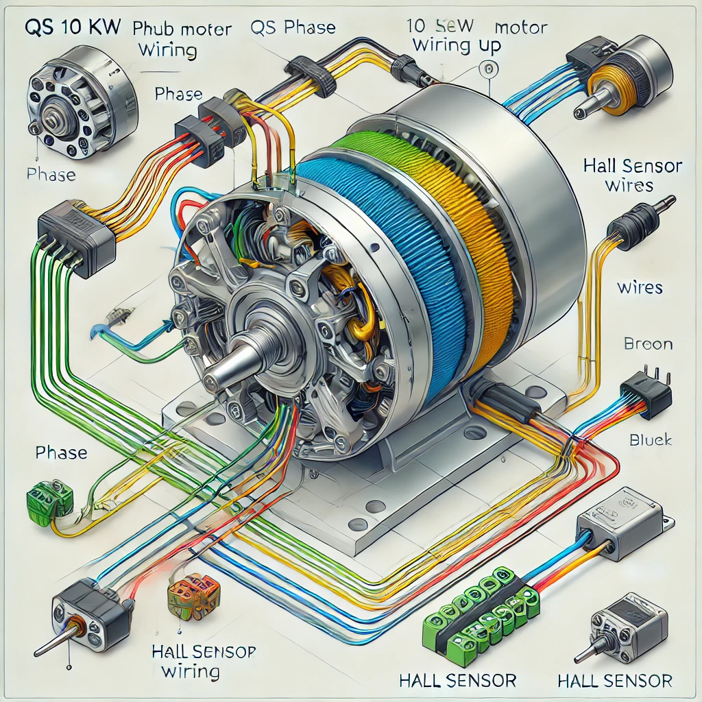
- Phase Wires:
- Yellow Wire: Phase A
- Green Wire: Phase B
- Blue Wire: Phase C
- Hall Sensor Wires:
- Red Wire: Supplies 5V power to the Hall sensors.
- Black Wire: Ground (GND).
- Yellow, Green, Blue Wires: Signal wires for Hall sensors A, B, and C, respectively.
- White Wire: Optional temperature sensor wire for monitoring motor temperature.
- Battery Wires:
- These wires connect the battery to the motor controller, supplying the power necessary to drive the motor. Proper sizing and connection are critical to handle the motor’s high power demands safely.
- Controller Connections:
- The controller acts as the brain of the system, managing power delivery, monitoring motor performance, and interpreting signals from sensors. Ensuring proper wiring between the controller and the motor is essential.
- Optional Components:
- Some versions of the QS 10 kW hub motor include additional features such as dual Hall sensors for redundancy, temperature sensors, or braking inputs. These components enhance safety and performance.
Read Also: Mazda 2025 New Models 11746: Innovations and Updates
The Importance of the QS 10 kW Hub Motor Wiring Diagram
A wiring diagram is a visual representation of the electrical connections within the motor system. For the QS 10 kW hub motor, the wiring diagram provides critical details about how the various wires, connectors, and components are interconnected. This document is indispensable for several reasons:
- Clarity: It eliminates guesswork by providing a clear and organized layout of the connections.
- Troubleshooting: In case of a malfunction, the diagram helps identify potential wiring issues.
- Safety: Incorrect wiring can lead to short circuits, damage to components, or even fire hazards. The diagram ensures safe and accurate installation.
- Efficiency: Proper wiring improves motor performance and efficiency, reducing energy losses and ensuring smooth operation.
Step-by-Step Guide to Wiring the QS 10 kW Hub Motor
To correctly wire the QS 10 kW hub motor, follow these steps while referring to the QS 10 kW hub motor wiring diagram provided by the manufacturer.
1. Prepare Your Tools and Materials
Before starting the wiring process, gather the necessary tools, including wire strippers, crimpers, multimeter, and appropriate connectors. Ensure you have the correct wiring diagram for your specific motor model.
2. Connect the Phase Wires
The three-phase wires (yellow, green, and blue) from the motor must be connected to the corresponding terminals on the controller. Double-check the wiring sequence to ensure they are aligned correctly. Incorrect connections can cause the motor to run improperly or not function at all.
3. Connect the Hall Sensor Wires
Identify the Hall sensor wires (red, black, yellow, green, blue) and connect them to the corresponding pins on the controller. If your motor includes a temperature sensor (white wire), connect it as specified in the wiring diagram.
4. Connect the Battery Wires
Securely connect the battery’s positive and negative terminals to the motor controller. Use connectors rated for the motor’s power requirements to prevent overheating or electrical failure.
5. Verify Connections
Before powering on the system, double-check all connections against the QS 10 kW hub motor wiring diagram. Ensure that all wires are securely attached and free from damage.
6. Test the Motor
Turn on the system and conduct a low-speed test to verify that the motor functions correctly. Monitor for any unusual sounds, vibrations, or errors, and make adjustments as needed.
Common Wiring Issues and Solutions
Even with a wiring diagram, issues can arise during installation. Below are some common problems and their solutions:
- Motor Does Not Start:
- Possible Causes: Incorrect phase wire connections, loose Hall sensor wires, or insufficient battery voltage.
- Solution: Recheck the phase wire alignment and secure all connections.
- Motor Runs in Reverse:
- Possible Cause: Phase wires are incorrectly connected.
- Solution: Swap any two phase wires to correct the direction.
- Overheating:
- Possible Causes: Excessive current, poor ventilation, or a malfunctioning temperature sensor.
- Solution: Check the wiring and ensure the motor is operating within its specified limits.
- Erratic Operation:
- Possible Causes: Damaged Hall sensors, loose connections, or interference.
- Solution: Test the Hall sensors using a multimeter and inspect all wiring for damage.
Best Practices for Wiring the QS 10 kW Hub Motor
To ensure a successful installation, follow these best practices:
- Use Quality Components:
- Invest in high-quality connectors, wires, and tools to ensure reliable connections and longevity.
- Follow Manufacturer Guidelines:
- Always refer to the official QS 10 kW hub motor wiring diagram and instructions provided by the manufacturer.
- Test Incrementally:
- Test the motor at low speeds before subjecting it to full power to identify potential issues.
- Secure Wiring:
- Use cable ties and protective sheathing to organize and secure wires, preventing damage or disconnections during operation.
- Monitor Performance:
- Regularly check the motor and wiring for signs of wear or damage, especially if used in demanding environments.
Conclusion
The QS 10 kW hub motor wiring diagram is an invaluable resource for ensuring the safe and efficient operation of this high-performance motor. By understanding the components, connections, and best practices outlined in this guide, you can confidently install and maintain the motor in your electric vehicle or other applications. Proper wiring not only maximizes performance but also enhances the longevity and reliability of the motor, making it a worthwhile investment for any EV enthusiast or professional. Whether you’re a seasoned engineer or a DIY hobbyist, the QS 10 kW hub motor offers a powerful and versatile solution for your mobility needs.


